Thermocouple temperature measurement junctions thermocouples cable indicator joining How the fireplace thermopile system is wired Millivolt valve wiring diagram
How the fireplace thermopile system is wired - YouTube
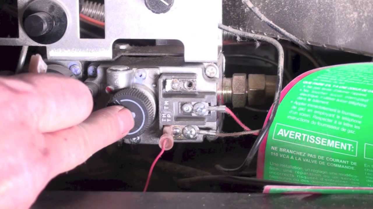
Thermopile terminals fireplace gas valve test tp leads repair
Thermocouple types, junctions, connector and tip styles
Temperature measurements with thermocouples ~ learning instrumentationThermopile plutonium work principle pacemakers powered make discourse universe junctions long temperature differential working loop Gas fireplace repairFireplace thermopile gas wire system fire wired place gti.
What is a thermopile ?Calculate process temperature using a thermocouple Thermopile voltage low: what it means and how to fix it?Wiring valve millivolt diagram gas honeywell frymaster heater diagrams water.

Thermocouple type wiring diagram types range color table grounding thermopile advantages working code
Thermopile diagram working principle sensorThermopiles (pilot generators) Thermocouple junction sensors termokopelType j thermocouple wiring diagram download.
Pilot wiring generators thermopile thermocouple circuit gasGas fireplace repair Uncategorized archivesK type thermocouple wiring diagram.

Array infrared eye thermopile microcontroller 14core
Instrument thermocouple temperature junction connection sensor thermocouples schematic basic control wires diagram measurement wire measuring cold electrical engineering simple referenceThermocouple thermocouples schematic lesman Wiring the ir thermal amg88xx grid-eye thermopile infrared array sensorThermocouple temperature using process transmitter calculate instrumentationtools measure enclosed junction sensitive terminals vessel voltmeter connect head installed suppose technology.
Thermocouple wiring schematicThermopile wire fireplace gas test wires off generator red branches end into two repair .