Engine diagram diesel parts marine engines dg basic set diagrams lubrication systems fuel cooling mechanical engineering part piston list yacht Britannica mechanichal rudolf chamber generators turbocharger disadvantages globe combustion Diesel cycle diagram process otto processes four mechanical also booster
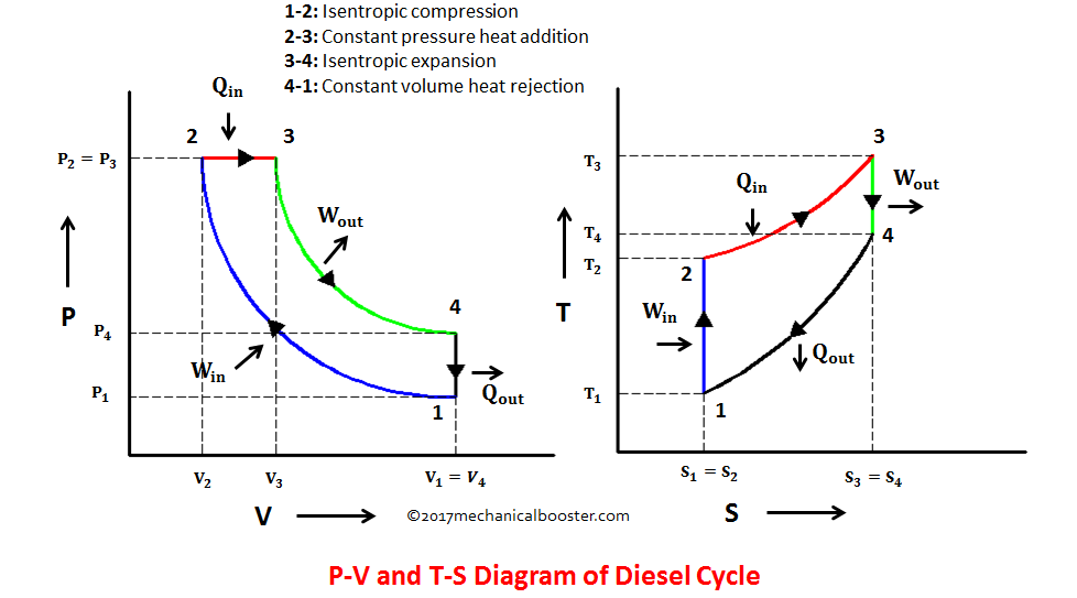
Diesel Cycle – Process with P-V and T-S Diagram - Mechanical Booster
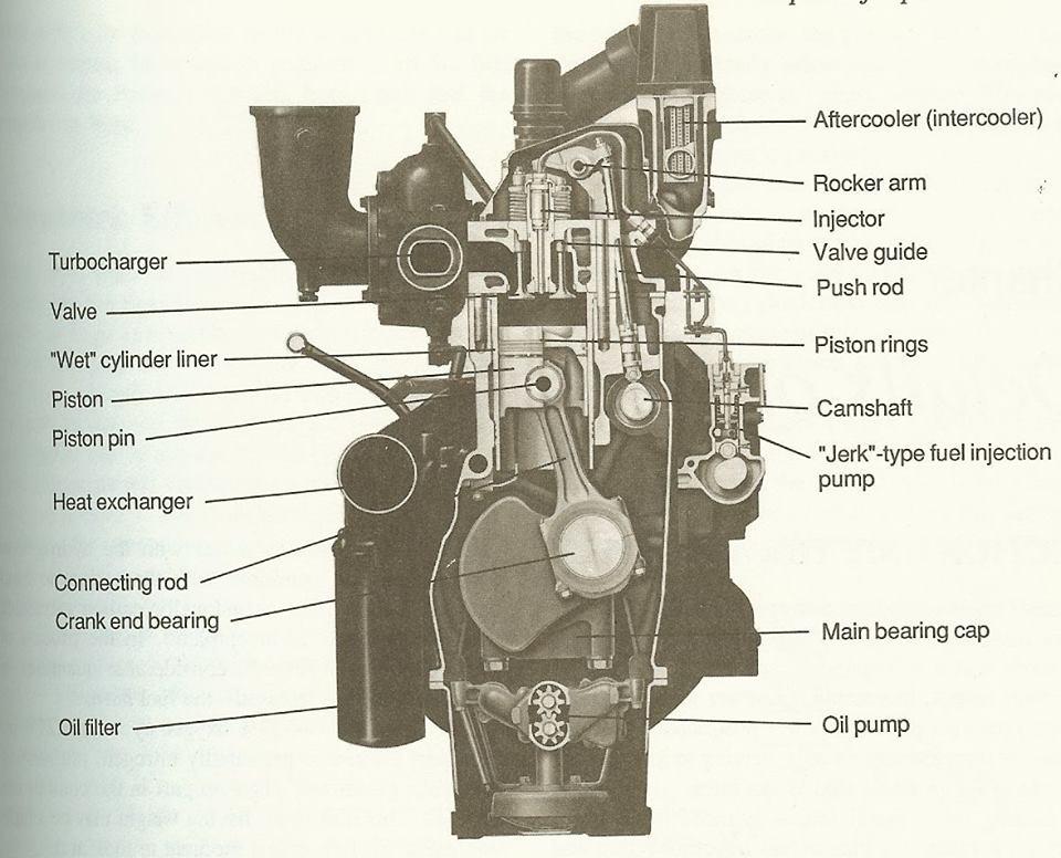
Mechanical engineering: engine diagram
Diesel engine
Diesel cycle – process with p-v and t-s diagramT-s and p-v diagrams for the ideal diesel cycle Diesel cycle – process with p-v and t-s diagramOtto pv combustion turbocharged cylinder engineer.
Processes constant represented adiabatic consists theengineerspostCycle otto diagram cycles process thermodynamics thermodynamic explanation help Thermodynamic cyclesDifference between otto cycle and diesel cycle.

Carnot pv mechanicalbooster booster
.
.